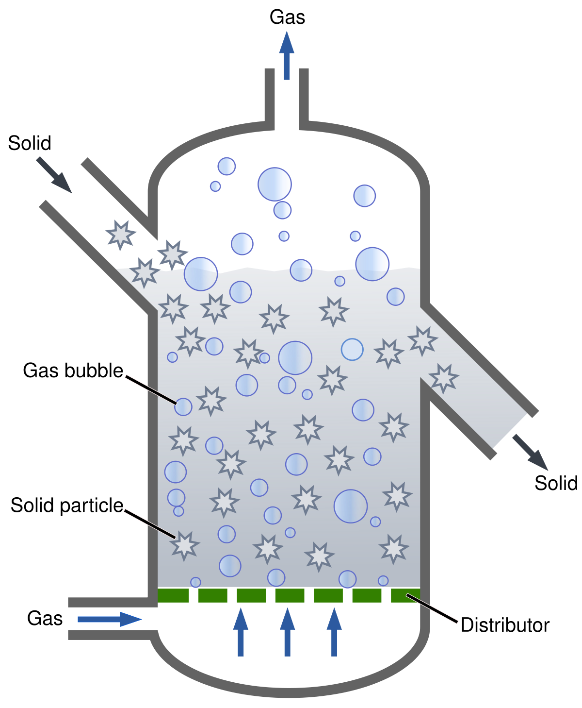
In this model the reactant gas enters the bottom of the bed and flows up the reactor in the form of bubbles. The most disadvantage with fluidized-bed reactors is that they require fairly little particles 23 mm to reduce heatmass transfer effects.

Bubbling Fluidized Bed Reactor With An Electrostatic Precipitator Download Scientific Diagram
Two dimensional bed of 1m height and 028 width is taken.
. 251 The Characteristic of Fluidized Bed 57 252 Combustion Characteristic of CFB Boiler 58 253 Development of Circulating Fluidized Bed Combustion Technology 58 254 Comparison Between Bubbling Fluidized bed and Circulating Fluidized Bed 59 26 Pulverized Coal Combustion 60 261 Furnace Type of Pulverized Coal Combustion 61. Jurnal Teknologi Sciences Engineering 58 2012 8588 In the design of bubbling fluidized beds the distributor 110 pressure drop ΔPd is maintained within a range of 15 to 30 of 100 the bed pressure drop ΔPb 312. Modeling the Bubbling Fluidized Bed Reactor BFB.
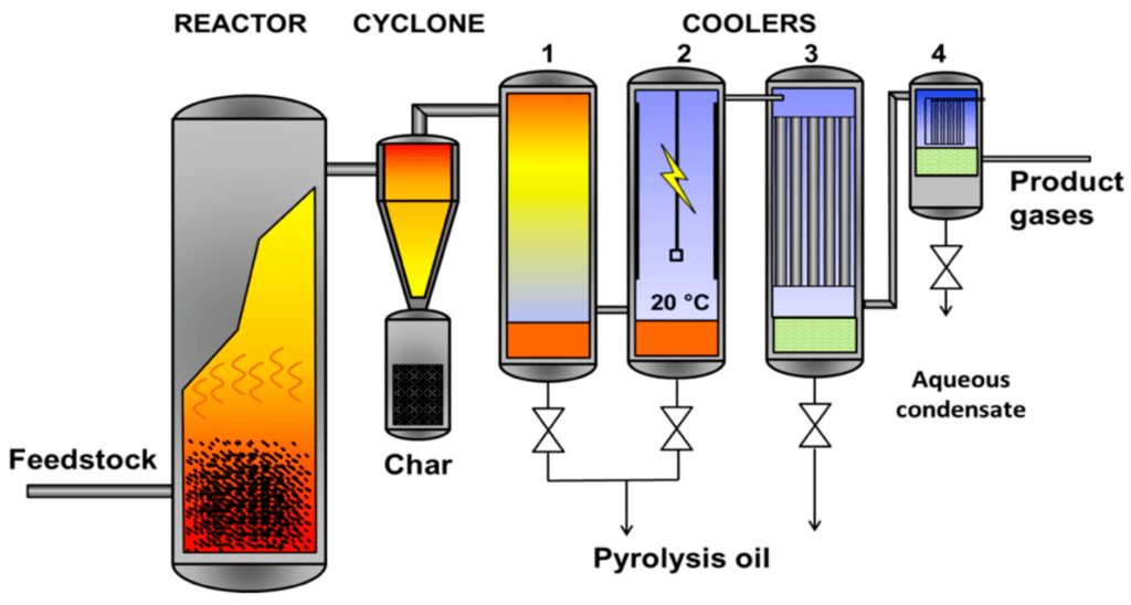
Feeding zone gasification. 4 heat transfer tubes. 3 particle recovery by means of cyclones.
Bubbling Fluidized Bed Reactor 4. The air-reactor is designed as a high-velocity riser and the fuel-reactor as low-velocity bubbling fluidized bed. The bubbles appear to be very similar to gas bubbles formed in.
2 bubble size control through small solid particle size or baffles. The yields from the larger units were found to be disastrously less than those obtained in the pilot plant unit. The IDAES Bubbling Fluidized Bed Reactor BFBR model represents a unit operation where two material streams a solid phase and a gas phase pass through a linear vessel while undergoing chemical reactions.
DESIGN AND CONSTRUCTION OF A FLUIDIZED BED by Robert Ryan Mota Bachelor of Science California State Polytechnic University Pomona 2010 A Thesis. The dual fluidized bed reactor is a recirculating system in which one half of the unit operates as a steam pyrolysis device for biomass. The design parameters which affect the.
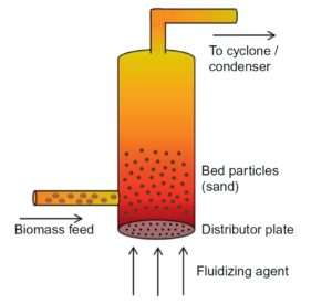
This is known as Packed Bed. As the bubbles rise mass transfer of the reactant gases takes place as they flow diffuse in and out of the. The pyrolysis of biomass starts in the bed reactor thanks to the high thermal exchange with the oxidant agent.
Widespread application of bubbling fluidised bed reactors to chemical processes has been hindered by some inherent drawbacks like the. A laboratory scale fluidized bed reactor was designed and fabricated successfully. In Brownsville Texas in 1950 two large 5-m-diameter bubbling fluidized bed FischerTropsch reactors were built based on the results from a 03-m-diameter pilot plant operated with a Group B iron catalyst.
Circulating fluidized bed reactor design and operation 39 --favourable turndown typically 41 and good load following capabilities. Principle Fluid Passes through Bottom with low velocity first to settle down the Solid Material on the Porous Plate called Distributor. Types Of reactor 1Bubbling Fluidized Bed 2Circulating Fluidized Bed 3Flash Reactor 4Annular Fluidized Bed 3.
A jet region around a single centrally arranged injector lance in a bubbling fluidized bed reactor is characterized by different parameters like. A typical fluidized bed reactor. Eventually if the gas velocity is increased continuously it will eventually become sufficiently rapid to carry the solid particles upward out of the bed.
Fine particle fluidization the FCC process was proposed was chosen commercial plants were built. Syngas is produced during the pyrolysis and exits the top of the reactor with the steam. Fluid passes through the voids of the solid material.
Reactants are pumped into the reactor through a distributor continuously causing the bed to become fluidized. This leads to costly needs for grinding lignocellulosic biomass. The reactor consists of three sections.
Numerical study of the hydrodynamics of a freely bubbling fluidized bed is studied here. Before the reactor is started the catalyst pellets lie on a grate at the bottom of the reactor. The disadvantages of fluidized beds are summarized below.
1 19 Pb H mf Nyakuma et al. Bubbling fluidized beds are composed by a grid air-distribution at the bottom of the reactor to allow a good uniformity of the oxidant agent in the biomass particles avoiding thermal gradients along the radius of the reactor. 5 solids circulation systems.
Consequently the proposed design of the bubbling fluidized bed gasifier for EFB briquette gasification will consist of three main parts. Part A gives general guidelines for the design of large commercial fluidized bed reactors with respect to the following aspects. Abstract A fluidized-bed reactor was designed and constructed for practical demonstration of the fluidization of solid particles at different fluid flow rates.
The pyrolysis occurs by introducing biomass and steam to a hot fluidized bed of inert material such as coarse sand. We are going to use the Kunii-Levenspiel bubbling bed model to describe reactions in fluidized beds. 1 solids properties and their effect on the quality of fluidization.
The bubbling fluidized bed is doubtless the foremost standard reactor for quick shift. Alternatively the fluidizing fluid can be substituted for any given. At velocities beyond this region the particles are well apart and the.
Equipment Design The movie below shows the operation of a fluidized bed reactor. The beds behavior after initial fluidization depends on. When this begins to happen the bubbling and agitation of the solids are still present and this is known as the region of fast fluidization and the bed is a fast-fluidized bed.
Octave Levenspiel Emeritus Professor Oregon State University During the Second World War the US had an urgent need to produce enormous quantities of aviation gasoline. New bubbling fluidized bed with vertically aligned vertical nozzles the fluid dynamics of the fluidized beds have to be determined and analysed especially the flow around the gas nozzles. The fluidized bed gasifier FBG is considered the most suitable reactor for biomass gasification due excellent mixing efficient heat temperature control and tolerance for fuels.
Bubbling Fluidization This type of fluidization has been called aggregative fluidization and under these conditions the bed appears to be divided into two phases the bubble phase and the emulsion phase. Nevertheless the fuel-reactor can be operated in the fast fluidization regime where the gas velocity is higher than in the bubbling regime to increase the fuel load 167. The bed of this reactor was sand particles of average size 1800 μm weighed 06 N and the fluidizing fluidwas air.
Bubbling beds of fine particles are difficult to predict and are less efficient Rapid mixing of solids causes non-uniform residence times for continuous flow reactors Particle comminuting breakup is common Pipe and vessel walls erode due to collisions by particles. A bed section b freeboard section and c conical closure section with inlet cone. This paper describes a pilot plant scale circulating fluidized bed unit recently designed constructed and put into operation in the Pulp and Paper Centre at the.
Bubbling Fluidized Bed Reactor Chemical Engineering World

Bubbling Fluidized Bed An Overview Sciencedirect Topics

Bubbling Fluidized Bed An Overview Sciencedirect Topics

Bubbling Fluidized Bed An Overview Sciencedirect Topics

Process Schematic For Bubbling Fluidized Bed Download Scientific Diagram

Schematic Diagram Of A Bubbling Fluidized Bed Reactor Download Scientific Diagram
Bubbling Fluidized Bed Reactor Chemical Engineering World
Fluidized Bed Reactor Wikipedia
0 comments
Post a Comment